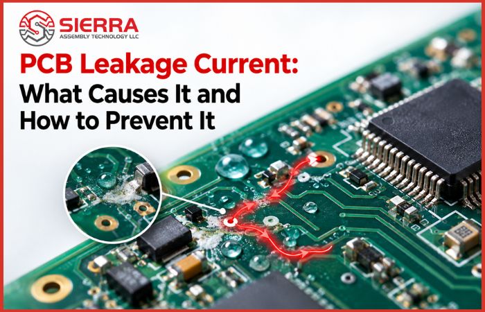
PCB Leakage Current: What Causes It and How to Prevent It

Sep 18,2026

What Is PCB Leakage Current?

PCB leakage current is unwanted electrical current that flows through an unintended path on a printed circuit board. Instead of remaining within the intended circuit path, a small amount of current can pass through the PCB surface, insulation material, contamination, or another unintended path between conductors.

A small amount of leakage can be normal in some electronic circuits. However, excessive leakage can affect circuit operation, especially in circuits that use high-impedance nodes or require accurate low-current measurements.

The exact acceptable leakage level depends on the circuit design, operating voltage, insulation requirements, and application.


What Causes Leakage Current on a PCB?

Several factors can create conditions for PCB leakage. The most common causes include:

1. Moisture and Humidity

  • Moisture on or within a PCB can reduce the effective insulation between conductive areas. In combination with contaminants on the board surface, moisture can create an unintended conductive path.
  • This is particularly important for electronics exposed to humid environments or changing environmental conditions.
2. Flux Residue and Ionic Contamination
  • Residues left after soldering can contribute to surface leakage when they contain or attract conductive contaminants. Ionic contamination is especially important because moisture can allow ions to move between conductors.
  • Proper cleaning and process control help reduce this risk when the assembly process requires cleaning.
3. Dust and Surface Contamination
  • Dust, handling residue, oils, and other contaminants can accumulate between closely spaced conductors. Depending on the material and environmental conditions, contamination can contribute to unwanted current paths.
  • Keeping PCB surfaces clean during manufacturing, assembly, handling, and storage helps reduce this type of problem.
4. Insufficient Creepage and Clearance
  • The distance between conductive features matters when a PCB must maintain electrical isolation.
  • Clearance is the shortest distance through air between conductive parts, while creepage is the shortest distance along the surface of an insulating material.
  • If the spacing does not meet the requirements of the application, the risk of unwanted conduction or other electrical problems can increase.
5. Damaged Solder Mask or PCB Surface
  • Solder mask provides insulation and protects the copper surface. Damage, defects, or contamination affecting the board surface can create conditions for leakage between nearby conductive areas.
  • Solder mask should not, however, be treated as the only insulation method when a design has specific electrical isolation requirements.
6. PCB Material and Insulation Issues
  • The insulating properties of the PCB material are important in applications where leakage and insulation resistance are critical.
  • Material selection should consider the board's operating voltage, temperature, humidity, frequency, and environmental conditions rather than choosing a material based on a single specification alone.

Common Sources of PCB Leakage

PCB leakage can originate from either the PCB itself or the assembly and operating environment.

Potential Source

How It Can Contribute to Leakage

Moisture

Provides conditions for surface conduction

Ionic contamination

Can create conductive paths when moisture is present

Flux residue

May contribute to surface leakage depending on residue characteristics

Dust and handling residue

Can contaminate insulation areas

Closely spaced conductors

Leave less surface distance for insulation

Damaged solder mask

Can expose or reduce protection around conductive areas

PCB material or process issues

May affect insulation performance

Assembly contamination

Can introduce unwanted conductive residue


Not every leakage problem has the same cause. The correct diagnosis requires looking at the PCB design, manufacturing process, assembly condition, and operating environment.

How PCB Leakage Current Affects Circuit Performance

The effect of leakage depends on the circuit and the amount of unwanted current.
In sensitive electronics, PCB leakage can result in:

  • Unexpected voltage readings
  • Incorrect sensor measurements
  • False triggering of high-impedance inputs
  • Unstable circuit behavior
  • Reduced insulation resistance
  • Unwanted current between isolated circuit sections
For example, a sensor circuit designed to detect very small changes in voltage may be affected by leakage that would have little noticeable effect on a higher-current circuit.

PCB Leakage Current vs. Short Circuit

PCB leakage and a short circuit are not the same problem.

Feature

PCB Leakage Current

Short Circuit

Current path

Unintended path with some resistance

Unintended low-resistance path

Typical current

Often relatively small

Can be significantly higher

Common causes

Moisture, contamination, insulation issues

Copper contact, solder bridge, conductive debris, component failure

Circuit effect

May cause subtle or intermittent behavior

Often causes immediate circuit malfunction

Detection

May require insulation or leakage testing

Often found through electrical testing or visual inspection

 
A PCB can therefore have a leakage problem without having a direct short between two conductors.

How to Test PCB Leakage Current

Testing should be based on the electrical requirements of the specific PCB and its application.

1. Leakage Current Measurement
A controlled voltage can be applied between specified conductors or circuit sections, and the resulting current can be measured. The test conditions need to match the applicable design or product requirements.
2. Insulation Resistance Testing
Insulation resistance testing evaluates how effectively a PCB or assembly prevents current from flowing between specified conductive areas.
This can be useful when the concern is isolation between circuits rather than normal circuit operation.
3. Visual and Process Inspection
Electrical testing is not the only way to investigate leakage. Visual inspection can help identify:

  • Visible contamination
  • Residue
  • Damaged solder mask
  • Solder bridges
  • Surface damage
  • Other manufacturing abnormalities
For reliable results, test methods and acceptance criteria should be defined according to the PCB design and application requirements.

How to Find the Source of PCB Leakage

When a board shows unexpected leakage, troubleshooting should be systematic.

1. Identify the Affected Circuit
Determine which circuit section or conductive areas are showing unexpected current.

2. Check for Contamination
Inspect the PCB surface for flux residue, moisture, dust, handling contamination, or other visible residue.

3. Check Insulation and Spacing
Review the affected areas for appropriate creepage and clearance, solder mask condition, and possible physical damage.

4. Compare Electrical Measurements
Measure the suspected circuit paths under controlled conditions and compare the results with the expected behavior.

5. Review Manufacturing and Assembly Conditions
If multiple boards show a similar problem, review fabrication, soldering, cleaning, handling, and storage processes. A recurring leakage issue may indicate a process-related cause rather than an isolated board defect.

How to Prevent PCB Leakage Current

Preventing leakage starts with controlling the factors that can create unintended conductive paths.
1. Use Appropriate PCB Spacing
Creepage and clearance should be designed according to the circuit's voltage, environment, applicable standards, and safety requirements.
2. Control PCB Cleanliness
Use appropriate manufacturing and assembly processes to control flux residue, ionic contamination, dust, and handling contaminants.
3. Protect the PCB From Moisture
PCB storage, handling, and environmental protection should be appropriate for the board material and application. Moisture exposure can be particularly important when insulation resistance is critical.
4. Select Materials for the Application
Choose PCB materials based on the electrical, thermal, mechanical, and environmental requirements of the product. Insulation performance should be considered when leakage is a design concern.
5. Protect Sensitive Areas When Required
For some applications, additional protection such as conformal coating may be appropriate. However, coating should be selected based on the actual environmental and electrical requirements and applied using a controlled process.
6. Include Appropriate Testing
Where leakage or insulation performance is important, define the appropriate inspection and electrical testing requirements before production. Finding the issue during manufacturing is generally more practical than discovering it after the product is deployed.

PCB Manufacturing and Assembly Factors That Can Cause Leakage

PCB leakage is not always caused by the circuit design. Manufacturing and assembly conditions can also affect the final electrical performance.
Important factors include:

  • PCB surface cleanliness
  • Flux and soldering processes
  • Handling procedures
  • Solder mask quality
  • Conductor spacing
  • Material selection
  • Moisture exposure
  • Inspection and electrical testing
For this reason, leakage-related requirements should be communicated clearly when requesting PCB fabrication or assembly. This allows the manufacturer to understand which electrical characteristics need particular attention.

When Is PCB Leakage Current a Concern?

PCB leakage becomes more important when a circuit depends on high insulation resistance or very small current levels.
Applications that may require closer attention include:

  • Sensor and measurement circuits
  • High-impedance analog circuits
  • High-voltage electronics
  • Medical electronics
  • Instrumentation
  • Safety-critical or reliability-focused electronics
The acceptable level of leakage depends on the specific circuit and operating conditions. A value that has little effect on one design may significantly affect another.

Why Choose Sierra Assembly?

Sierra Assembly supports customers with PCB manufacturing and assembly for prototype, low-volume, and production requirements.
Our team provides U.S.-based engineering support and works with customers to understand PCB design, manufacturing, assembly, inspection, and testing requirements.
With more than 30 years of experience, Sierra Assembly supports quality-focused PCB production with ISO 9001:2015 and AS9100D certifications and capabilities for inspection and assembly requirements.
If PCB leakage, insulation, contamination, or other electrical performance requirements are important to your project, our team can review your requirements and help determine an appropriate manufacturing and assembly approach.

Frequently Asked Questions

1. Can flux residue cause PCB leakage current?
Ans: Yes. Depending on the type of flux residue and environmental conditions, residue can contribute to surface leakage. Moisture and ionic contamination can make this issue more significant.

2. Does moisture increase PCB leakage?
Ans: Moisture can reduce effective surface insulation and create conditions for unwanted current between conductive areas. The effect depends on the PCB material, contamination level, circuit design, and environmental conditions.

3. Can PCB leakage occur without a short circuit?
Ans: Yes. Leakage current can flow through an unintended path that has measurable resistance, so the board does not necessarily have a direct short circuit.

4. Can cleaning reduce PCB leakage?
Ans: Cleaning can reduce leakage when contamination or residue is contributing to the problem. The appropriate cleaning method depends on the PCB materials, components, assembly process, and manufacturer's requirements.
5. How can I prevent leakage current during PCB manufacturing?
Ans: Start with appropriate conductor spacing and material selection, control contamination and moisture, maintain soldering and handling processes, and define the required inspection and electrical testing before production.