Broken PCB Trace Repair Guide: Causes, Repair Methods, Tools & Challenges

Jun 01,2026
Printed circuit boards are the foundation of modern electronics. From industrial automation systems to consumer electronics and medical devices, every PCB depends on copper traces to maintain proper electrical connectivity. When a broken PCB trace interrupts signal flow, the entire device can stop working or behave unpredictably. In many cases, a broken trace PCB issue can lead to intermittent performance problems, signal loss, or complete circuit failure if not repaired properly.

A broken circuit board does not always mean the board must be replaced. In many cases, repairing damaged traces can restore functionality and extend the life of the assembly. Understanding how to fix a broken circuit board properly helps engineers, technicians, and electronics manufacturers reduce downtime and avoid unnecessary replacement costs.

This guide explains the common causes of PCB damage, how to repair a broken circuit board safely, and the best methods for fixing broken PCB traces in professional electronic assemblies.

What Is a PCB Trace?

A PCB trace is a thin copper pathway etched onto a printed circuit board that carries electrical signals and power between components such as resistors, capacitors, connectors, and microcontrollers. These conductive paths act like built-in wiring, allowing the circuit board to function efficiently and maintain reliable communication between electronic components.

Key PCB Trace Design Parameters

The physical dimensions of a PCB trace are carefully engineered to ensure safe electrical performance, proper signal transmission, and long-term reliability.
  • Trace Width: Wider traces can handle higher current loads without overheating, while narrow traces are commonly used for low-power signal routing and compact PCB layouts.
  • Copper Thickness: Trace thickness, typically measured in ounces of copper per square foot, affects the current-carrying capability and thermal performance of the circuit.
  • Trace Spacing: Adequate spacing between adjacent traces helps prevent short circuits, signal interference, and electrical crosstalk, especially in high-speed PCB designs.
                                                      

Common Causes of Broken PCB Trace Problems

A broken PCB can occur for several reasons. Identifying the root cause is important before attempting repairs.
  • Overheating: Excessive heat generated by high-power components or poor thermal management can weaken copper traces over time. Continuous thermal stress may cause traces to lift, crack, or burn completely.
  • Physical Damage: Dropping a board, bending it during installation, or improper handling can easily create a broken circuit board. Flexible and thin PCBs are especially vulnerable to mechanical stress.
  • Corrosion and Moisture: Moisture exposure and contamination can corrode copper pathways. Corrosion often causes intermittent connectivity issues and eventually leads to a broken trace PCB failure.
  • Poor Soldering Techniques: Improper soldering is another common reason for PCB broken trace problems. Excessive heat can damage copper pads and nearby traces, especially during rework.
  • Manufacturing Defects: Low-quality materials, weak copper adhesion, or improper fabrication processes can create long-term reliability issues in printed circuit boards.
  • Signs Your PCB May Have a Broken Trace
Many electronic failures are linked to hidden PCB damage. Common warning signs include:
  • Device not powering on
  • Intermittent operation
  • Burn marks on the PCB surface
  • Failed continuity tests
  • Components losing connection
  • Visible cracks or lifted copper traces
If you notice these issues, inspecting the board for broken PCB traces should be one of the first troubleshooting steps.

Tools Needed to Repair Broken Circuit Boards

Repairing a broken circuit board requires precision tools and careful handling.

PCB Repair Tool

Function

Soldering Iron

Repairs damaged electrical connections and broken PCB traces

Soldering Flux

Helps solder flow smoothly and improves bonding strength

Digital Multimeter

Checks continuity, resistance, and electrical connectivity

Thin Copper Wire

Rebuilds or bridges damaged trace sections

Conductive Ink Pen

Restores fine or hard-to-reach PCB traces

Precision Tweezers

Handles delicate repair materials and small components

Isopropyl Alcohol

Cleans oxidation, debris, and residue from the PCB surface

Magnifying Glass or Microscope

Helps inspect tiny cracks, lifted pads, and broken trace PCB damage


How to Fix a Broken Circuit Board Step by Step

Understanding how to fix broken circuit board traces properly can help restore performance and reliability.

Step 1: Inspect the PCB: Carefully examine the damaged area using magnification. Look for cracks, burnt copper, lifted pads, or disconnected traces. A multimeter can help identify open circuits and continuity failures.
Step 2: Clean the Surface: Before beginning repairs, clean the damaged area using isopropyl alcohol. Removing dirt, oxidation, and debris improves solder bonding and conductive ink adhesion.
Step 3: Remove Damaged Copper: Use a precision knife to scrape away damaged portions of the trace. Expose clean copper on both sides of the broken section.
Step 4: Apply Flux: Flux helps solder flow evenly and creates stronger electrical connections during repair.
Step 5: Repair the Broken PCB Trace
  • The repair method depends on the severity of the damage.
  • For small cracks, a solder bridge may restore continuity.
  • For larger gaps, thin copper jumper wires provide a more reliable connection.
  • Fine SMT traces may require conductive ink pens designed for PCB repair applications.
Step 6: Test Continuity: After completing the repair, test the trace with a multimeter to verify electrical continuity.
Step 7: Protect the Repaired Area: Applying conformal coating or epoxy helps protect repaired traces from moisture, corrosion, and mechanical stress.

Best Methods for Fixing Broken PCB Traces

Different repair methods work better for different types of PCB damage.

Repair Method

Best Application

Conductive Ink

Fine SMT traces

Jumper Wire

Large broken trace gaps
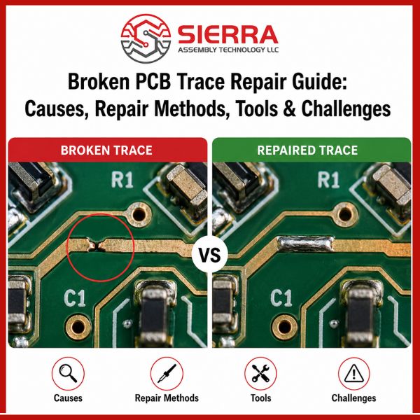
Solder Bridge

Minor cracks

Copper Tape

Medium-size damaged areas

 
Choosing the correct repair approach improves long-term durability and electrical performance.

Challenges of Repairing Multilayer PCBs

Multilayer PCB assemblies are more difficult to repair because internal traces may also be damaged. In many cases, the visible damage is only part of the problem.
Complex multilayer boards may require:

  • X-ray inspection
  • Micro-soldering
  • Internal layer diagnostics
  • Controlled impedance analysis
For high-reliability electronics, professional repair services are often recommended instead of attempting DIY repairs.

When PCB Repair Is Not Recommended

Although many damaged boards can be restored, some situations make replacement the better option.

PCB replacement may be necessary when:
  • The substrate is severely burned
  • Multiple layers are damaged
  • Delamination is present
  • High-frequency traces are compromised
  • Safety-critical circuits are affected
Understanding when to repair broken circuit board assemblies versus replacing them helps reduce long-term reliability risks.

How Professional PCB Manufacturing Helps Prevent Trace Damage

Many PCB failures can be prevented through proper manufacturing practices and quality control.

At Sierra Assembly, advanced PCB manufacturing processes help reduce the risk of broken PCB trace issues through:

  • IPC-compliant fabrication standards
  • High-quality copper materials
  • Automated optical inspection
  • Thermal management optimization
  • Controlled impedance design
  • Professional PCB testing services
  • Conformal coating protection
Reliable PCB manufacturing improves electrical performance, reduces field failures, and extends product lifespan.

Tips to Prevent Future PCB Trace Damage

  • Avoid excessive heat and maintain proper cooling
  • Handle PCBs carefully to prevent physical stress
  • Store boards in dry, anti-static packaging
  • Use proper soldering techniques and controlled temperatures
  • Inspect PCB traces regularly for cracks, corrosion, or discoloration

Conclusion

A broken PCB trace or damaged circuit board can affect overall device performance and reliability. Using the right repair techniques, tools, and inspection methods can help restore electrical connectivity and extend PCB lifespan. For reliable PCB manufacturing, quick-turn assembly, and prototype-to-production support, Sierra Assembly provides high-quality solutions for complex electronic applications.

Frequently Asked Questions

1. Can a broken PCB trace be repaired?
Ans: Yes, many broken PCB traces can be repaired using solder bridges, conductive ink, copper tape, or jumper wires depending on the severity of the damage.

2. What causes a broken circuit board?
Ans: A broken circuit board may result from overheating, moisture exposure, corrosion, poor soldering, physical stress, or manufacturing defects.

3. How do you test a repaired PCB trace?
Ans: A multimeter is commonly used to test continuity and verify that the repaired trace conducts electricity properly.

4. Is it better to repair or replace a broken PCB?
Ans: Minor trace damage can often be repaired successfully. However, severely burned, multilayer, or delaminated boards may require replacement.

5. Can multilayer PCBs be repaired?
Ans: Yes, but multilayer PCB repair is more complex because internal traces may also be damaged. Professional inspection and repair services are often recommended.

Why Choose Sierra Assembly?

Sierra Assembly delivers reliable PCB manufacturing and assembly solutions for industries that demand high performance, precision, and consistency. From prototype development to full-scale production, our team supports complex electronic projects with advanced manufacturing capabilities and engineering expertise.

Key advantages of working with Sierra Assembly include:
  • IPC-compliant PCB manufacturing and assembly processes
  • AS9100 Rev-D & ISO 9001:2015 certified quality standards
  • Fast 24-hour delivery options for urgent PCB requirements
  • Quick-turn PCB assembly and prototype manufacturing support
  • Prototype-to-production scalability for growing projects
  • Advanced PCB inspection and testing services
  • Engineering assistance for design optimization and manufacturability
  • High-reliability PCB solutions for aerospace, industrial, medical, and commercial applications
  • Strict quality control processes to reduce defects and improve long-term reliability
  • Dedicated customer support and responsive project management
Sierra Assembly Technology LLC is committed to delivering dependable PCB assembly and manufacturing solutions that help customers accelerate production timelines while maintaining exceptional quality and performance.

Need reliable PCB manufacturing or quick-turn assembly support? Sierra Assembly provides high-quality PCB assembly, prototype-to-production services, advanced testing, and engineering expertise for complex electronic applications. Contact our team today to discuss your PCB project.