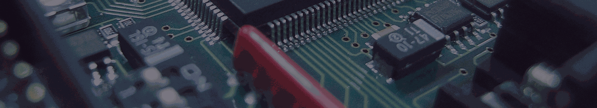
Printed Circuit Boards (PCBs) have become an essential product for many industrial applications. They do not take up much space in an application, nor do they add immense weight to the application product. They minimize electric noise in the product, and are easy to maintain and repair. In this post, we shall be discussing the PCB soldering process.
Pre-soldering Procedures
As there are a variety of procedures within soldering, we shall be focusing on soldering preparation and component removal phases.
-
Consolidate the Required Materials: For this procedure, you will require the following materials:
-
General purpose cleaner
-
Desolder tool
-
Soldering iron, solder, flux
-
Desolder Braid
-
Microscope
-
Wipes
-
Choose the Right Soldering Iron Tip: The rule of thumb for this step is that the larger the iron tip, the faster the rate of heat transfer. The tip should not extend too far beyond the edges of the joint. Also, you will need to choose the solder iron tip required for component removal.
-
Prepare the Board: Begin by cleaning all PCB components of any kind of contamination. You should ensure that the cleaning method or solution does not damage any of the parts. Next, remove any moisture on the board by lightly baking the PCB in an industrial oven. To protect the component leads, you can tin them before starting the soldering process.
-
Remove Excess Solder: This step is performed for a few important reasons. One is that a previously soldered component will have the original solder sticking to the pad. Reheating the solder will affect its physical composition, and it will not last long. The second point is that solder needs to remain ductile in order to absorb the stresses of expansion and contraction caused by heating and cooling. The third point is that excess solder can cause problems when placing a new component on the board.
PCB Cleaning Procedure
Generally, a vacuum powered desoldering tool is recommended for this procedure. The desoldering tool has a heated tip with a hole in the center to vacuum melt the solder.
-
Inspect the hole: Solder in the pad provides for proper heat transfer. If there is insufficient solder covering the pad, the hole should first be filled with solder. Filling the hole improves the thermal linkage between the desolder tool tip and the solder in the hole. This ensures rapid melting, and reduces potential for pad or hole damage.
-
Melt the Solder: Place the heated desoldering tip onto the pad until you feel the solder melt. Do not apply any downward or sideways pressure on the pad. After the solder melts, activate the vacuum and suck the solder through the hole in the tip into the solder storage chamber.
-
Apply the Solder: After the solder is vacuumed from the hole, continue the vacuum for an additional few seconds to make sure that the solder has had enough time to travel through the tip into the storage chamber. Apply the solder and then insert the component. Once this has been completed, clean the area.
Following these steps will ensure that the PCB soldering process is performed quickly and efficiently.